Axis controller UPAN “Rare”

99,00  excl VAT

The Axis stepper motor controller allows you to easily control the motion of your machinery, helping them perform tasks accurately and efficiently. With our product, you can control the motion of your stepper motor with high precision and monitor its operation using modern technologies. Our controller is a reliable and efficient solution for your business or private project, enabling you to move forward and reach new heights.


Due to high demand, all our controllers are currently sold out.
We are now waiting for the next batch of boards to arrive.
All orders will be shipped in full starting from 18-09-2025.

We sincerely apologize for the inconvenience and thank you for your patience!

EU shipping by GLS or DHL (up to 5 days)

USA, Canada shipping DHL (up to 5 days)


WIKI:  https://www.cnc.house/firmware-update-manual-for-the-upan-stepper-motor-controller


UPAN powerful features

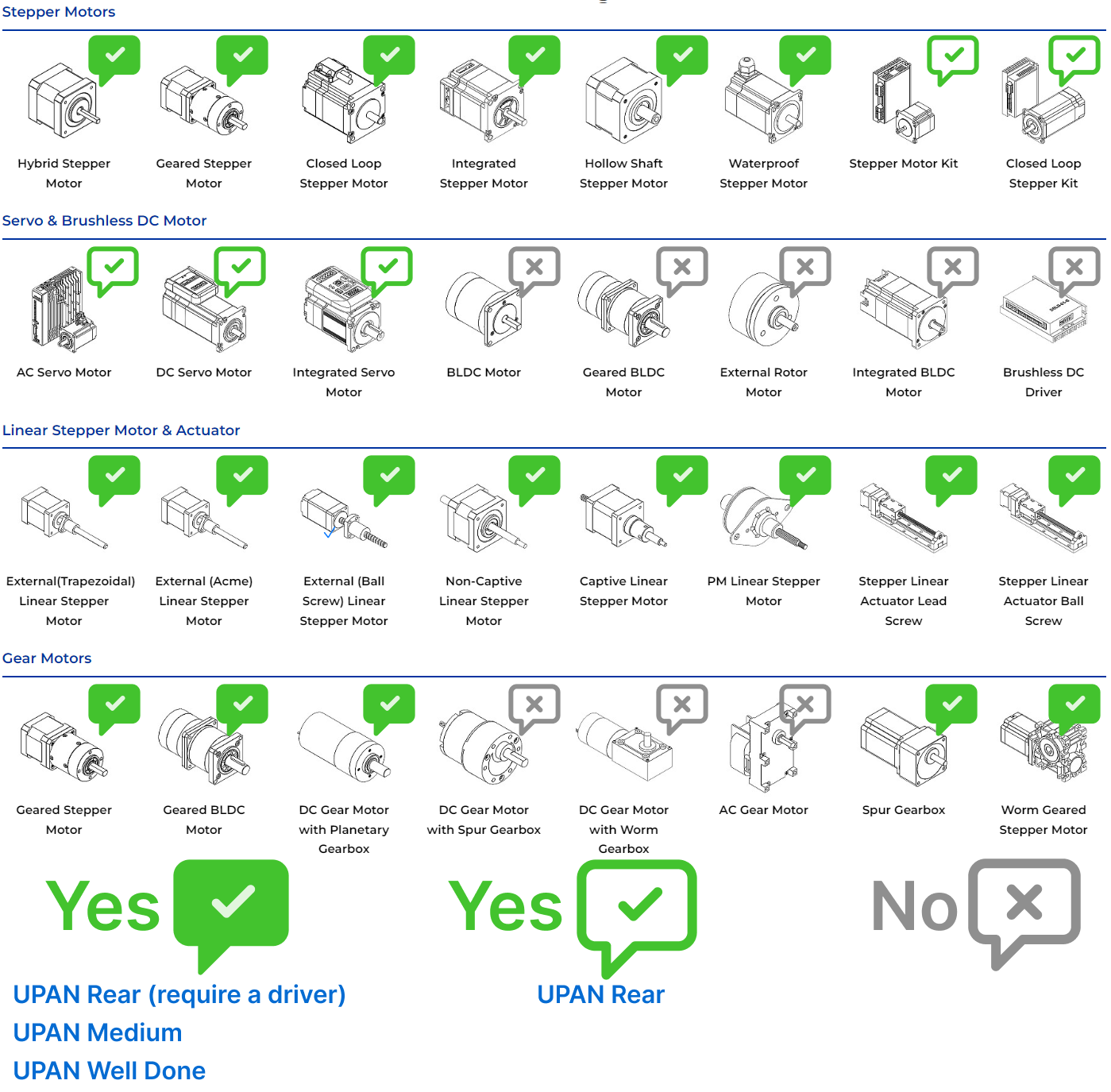
Versatile motor control:

The Axis Controller UPAN is designed to control a wide range of stepper motors, from small ones used in 3D printers to large industrial servomotors.

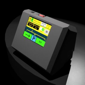
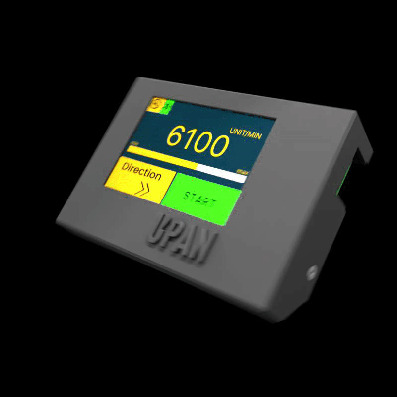
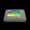
User-friendly touchscreen interface: 

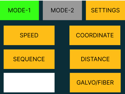
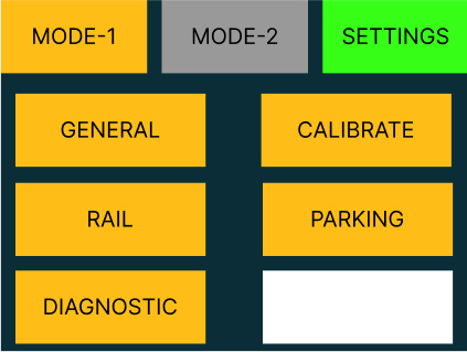
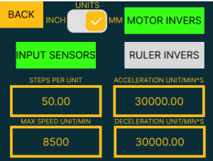
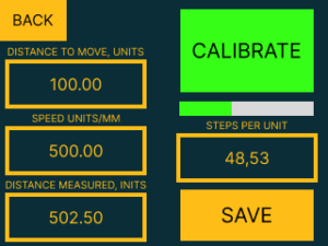
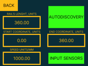
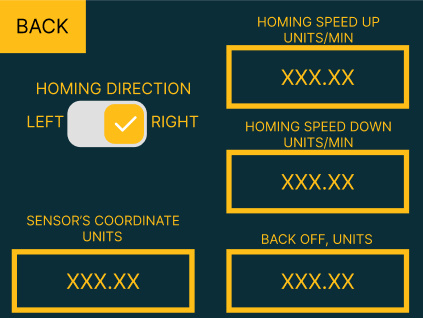
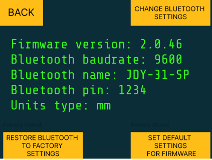
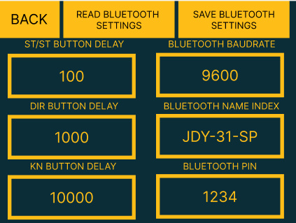
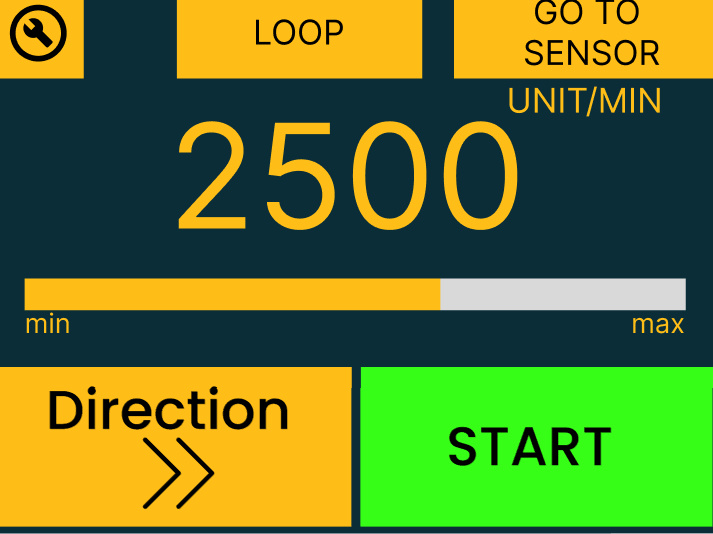
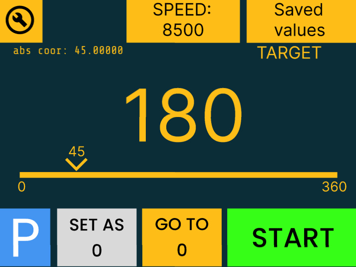
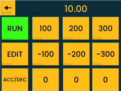
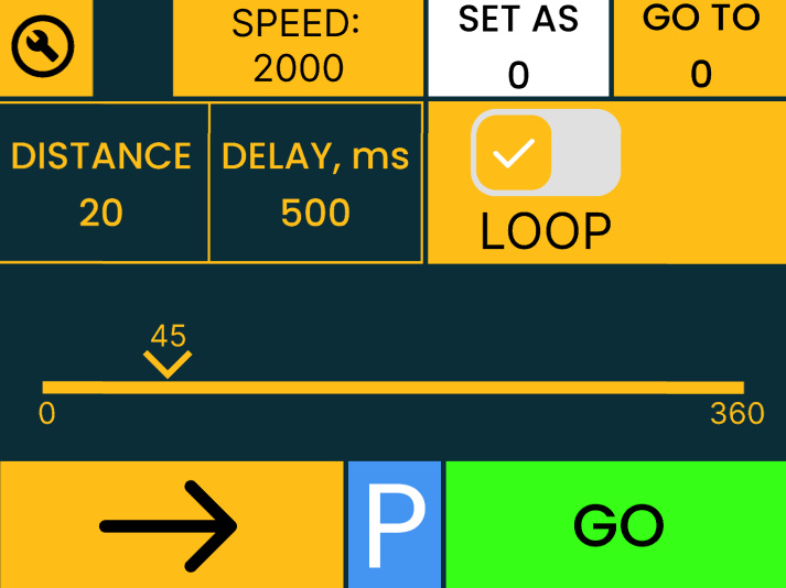
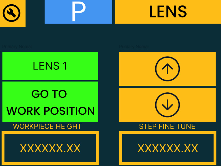
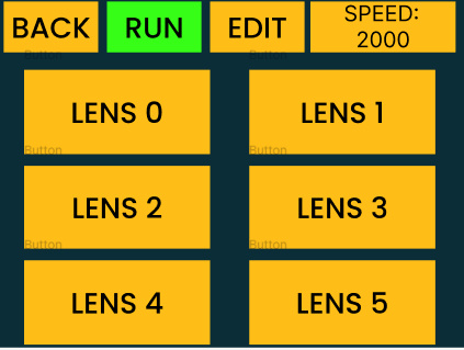
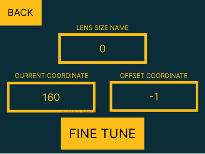
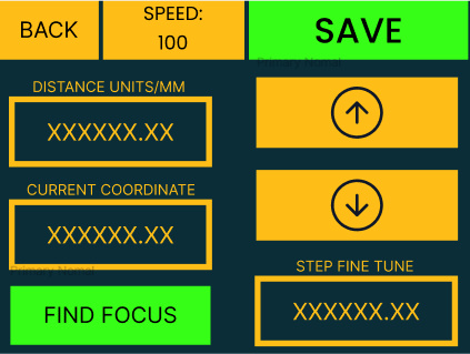
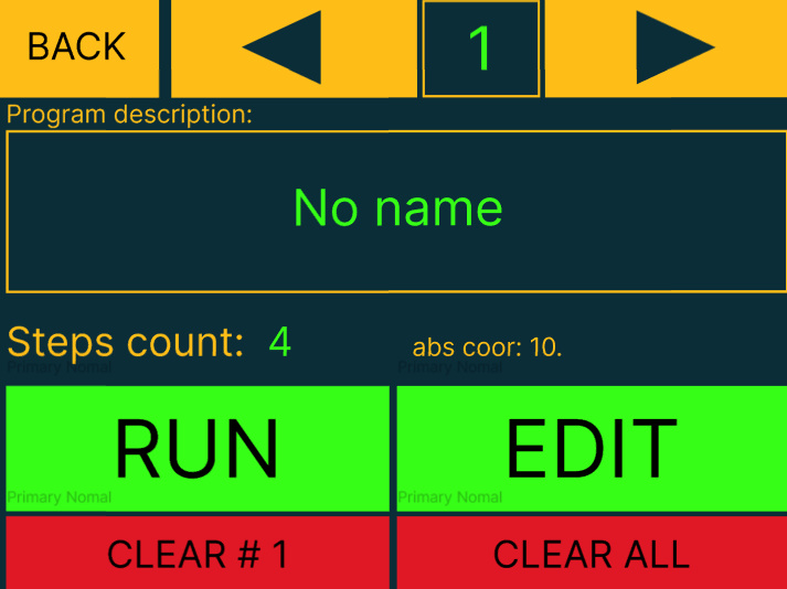
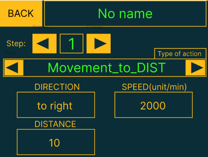
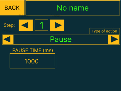
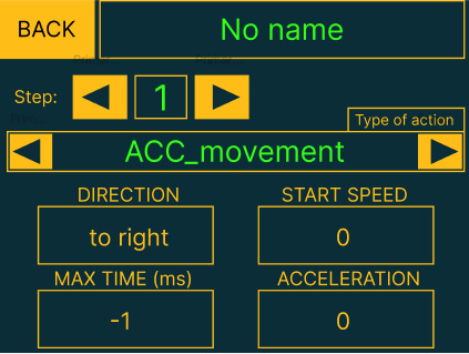
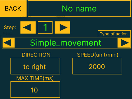
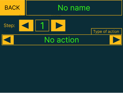
The controller features a large and intuitive touch screen interface, designed with the user in mind. The interface provides easy access to all motor control functions and configuration options. The touch screen display allows for precise control over motor movement, with real-time feedback on motor speed, position, and direction. The interface is easy to navigate, with clearly labeled buttons and icons, making it easy to set up and configure the controller for any motor application. Whether you are a beginner or an experienced user, our user-friendly interface makes controlling your motor a breeze.

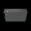
The Axis Controller UPAN is designed to be both compact and durable, making it a reliable solution for a wide range of motor control applications. Whether you need to control small stepper motors for your 3D printer or larger industrial servo motors, the Axis Controller UPAN is up to the task. Its rugged design means it can handle demanding environments and challenging conditions, so you can rely on it to keep your motors running smoothly and efficiently. And with its compact size, it’s easy to mount and install, even in tight spaces.

UPAN controller technical characteristics:

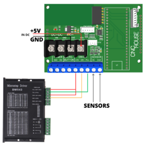
  • UPAN stepper motor controller
  • All type of Nema and Servo stepper motors
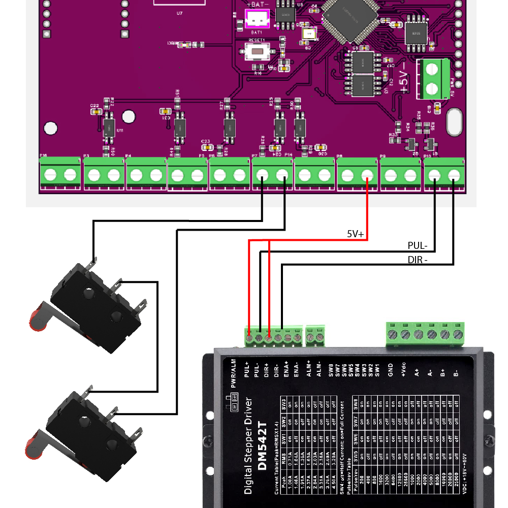
  • Step/Dir signals
  • Touchscreen display 3,2″
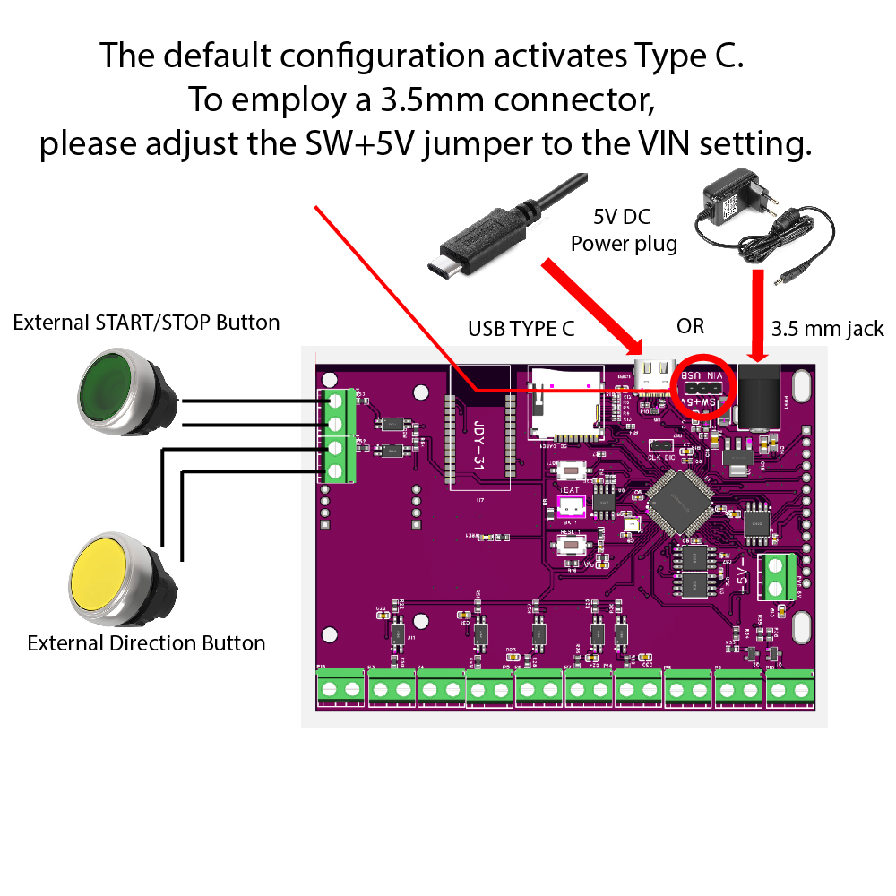
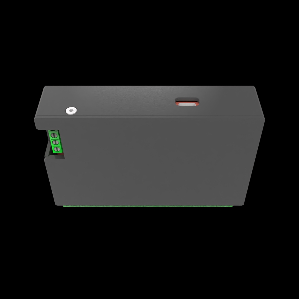
  • Type C power plug 5 V
  • End switch for hardware limits
  • Inputs for 2 external button or triggers
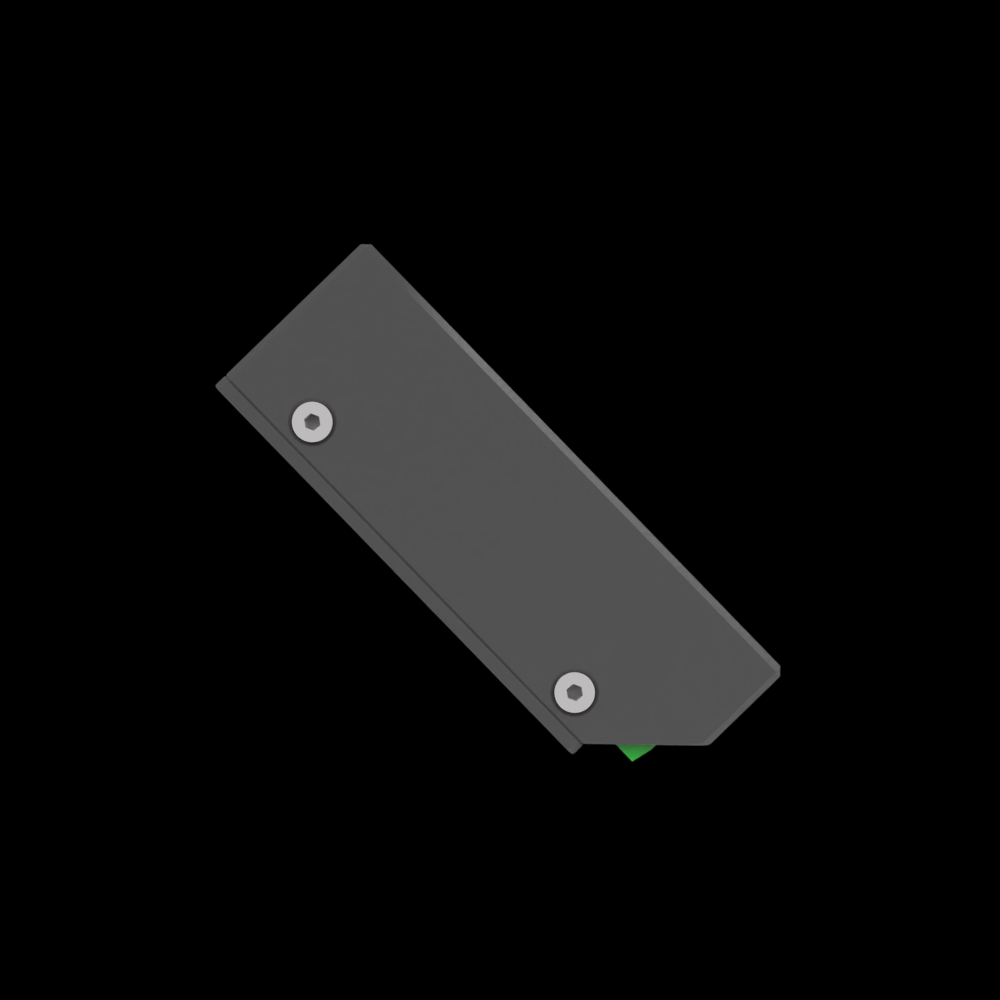
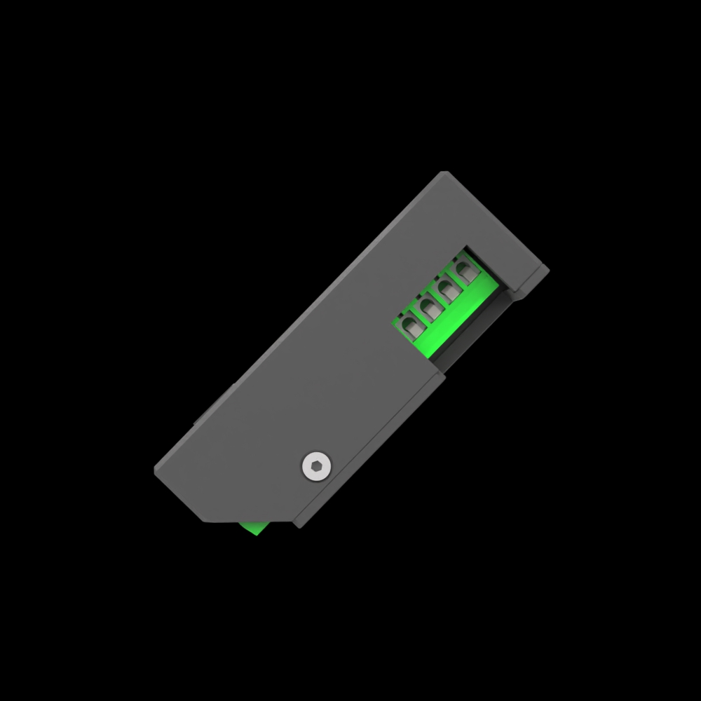
  • Dimensions: 113 mm(L) x 80 mm (H) x 28 mm (D)
  • Weight: 190 gr


Download the 3D Model for UPAN Controller Generation 3.0

For those interested in customizing or exploring the physical dimensions of the UPAN Controller Generation 3.0, we have made a 3D model of the enclosure available for download. This model, created in Autodesk Fusion, can assist in understanding the layout and designing any necessary mounts or modifications.

Access the 3D model by following this link: Download 3D Model

Please note, the link will direct you to a resource where you can easily download the model for your use. The model provides a detailed representation of the enclosure, allowing for precise customization and integration.


How it works

Designed to control the movement of a stepper motor, whether it’s a small motor for a 3D printer or a large industrial servo motor. Equipped with a touch screen for easy control, our controller can also be connected to a PC or our own Android app via Bluetooth, allowing you to control your motor with modern technology.


Weight 0,19 kg
Dimensions 113 × 80 × 28 mm

Menu Manual

MAIN MENU

SETTINGS

SETTINGS -GENERAL

UNITS: Toggle the measurement units between inches and millimeters for machine operations.

INPUT SENSORS: Access end switch

MOTOR INVERS: Reverse the direction of motor operation if necessary to ensure correct movement.

RULER INVERS: Invert the readings from the ruler.

STEPS PER UNIT: Set the number of steps the motor must make to move the machine by one unit of measurement.

ACCELERATION UNIT/MIN²: Define the rate of change of speed per minute squared for accelerating movements.

MAX SPEED UNIT/MIN: Establish the maximum speed limit of the motor per unit of measurement per minute.

DECELERATION UNIT/MIN²: Set the deceleration rate, controlling how quickly the machine slows down per minute squared.

SETTINGS – CALIBRATE

DISTANCE TO MOVE, UNITS: Set the intended travel distance for the calibration process.

SPEED UNITS/MM: Input the speed for the calibration move in units per millimeter.

DISTANCE MEASURED, UNITS: Enter the actual distance that the device has traveled during the calibration process for accuracy assessment.

CALIBRATE: Initiate the calibration sequence to ensure accuracy in movements.

STEPS PER UNIT: Displays the calculated number of motor steps per unit that the controller automatically determines by comparing the desired travel distance with the actual distance moved during calibration.

SAVE: Save calibration settings into the system.

SETTINGS – RAIL

The AUTODISCOVERY feature operates on a straightforward principle designed to automate the measurement of the rail’s length. Here’s the process breakdown:

  1. AUTODISCOVERY Activation: Upon pressing the AUTODISCOVERY button, the device initiates the calibration process by moving in one direction towards the first endpoint.
  2. INITIAL ENDPOINT DETECTION: The device continues to move until it triggers the end sensor, marking one endpoint of the rail.
  3. DIRECTION REVERSAL: After reaching the first endpoint, the device reverses its direction and travels towards the opposite end of the rail.
  4. SECOND ENDPOINT DETECTION: The device stops upon triggering the second end sensor, which marks the other maximum point of the rail.
  5. MEASUREMENT CALCULATION: Based on the distance traveled between the two endpoints, the controller automatically calculates and sets the rail’s length.
  6. After the AUTODISCOVERY feature locates the second endpoint, the device will automatically return to the starting position, completing the calibration process. This ensures that the system is ready for precise operations from the designated origin point.

Additionally, the following settings can be adjusted:

  • SPEED UNITS/MM: Specifies the speed at which the AUTODISCOVERY process operates.
  • RAIL’S LENGTH, UNITS: Manually enter the total length of the rail if known, useful for setups like a rotary axis where the length corresponds to the degree of rotation (e.g., 360 units for a full turn).
  • START COORDINATE, UNITS and END COORDINATE, UNITS: Manually set the starting and ending points of the rail, which can be utilized when AUTO-DISCOVERY is not necessary or when working with preset limits.

For AUTODISCOVERY to function correctly, end sensors must be connected and activated within the controller’s settings, ensuring they are ready to detect the machine’s movement and set the rail’s length accurately.

Settings – Parking

HOMING DIRECTION: Select the direction in which the machine should move to find the home position, which is marked by the end sensor also acting as the hard limit.

HOMING SPEED UP, UNITS/MIN: Set the speed at which the machine moves towards the home sensor.

HOMING SPEED DOWN, UNITS/MIN: Determine the speed at which the machine moves away from the home sensor after triggering it. This is set at a lower rate to fine-tune the machine’s position to the exact home location.

SENSOR COORDINATES (UNITS): Defines the absolute coordinate value assigned to the sensor’s trigger point. Example: If the sensor is mounted physically 10 mm away from the true mechanical end of the rail, you can set the coordinate to 10 so your working area matches real-world limits.

BACK OFF, UNITS: Define the offset distance the machine must travel away from the machine home to establish the working zero point. This offset ensures the start of operations occurs at a predefined position from the machine’s home.

DIAGNOSTIC:

BLUETOOTH CURRENTLY NOT AVAILABLE

Is used to showcase the firmware version, bluetooth settings and can be used to factory reset the bluetooth or device settings, as well as change the bluetooth settings.

BLUETOOTH SETTINGS:

Allows the user to change the bluetooth button delays, bluetooth name as well as the pin and baudrate.

MODE – SPEED

START/STOP Button: Press to start or stop the machine’s movement. This function is accessible via the on-screen button or can be managed with an external physical button. The external button uses a standard switch mechanism activated by a 5-volt signal for compatibility with various setups. For connecting external buttons, refer to the “External Button Connection Diagram” for proper setup.

DIRECTION Button: Alters the direction of the machine’s movement. This too can be controlled by an on-screen option or an external switch, facilitating quick directional adjustments during operation. It also operates with a 5-volt signal. Make sure to consult the “External Button Connection Diagram” for correct installation.

LOOP Button: Enable repetitive movement.

GO TO SENSOR Button: Initiate homing by moving to the end-stop.

MODE – COORDINATE

SPEED: Allows you to set the speed at which the machine will move during operations.

TARGET POSITION: The large number represents the target coordinate the machine will move to, which is input through a digital keypad that appears upon selection.

SCALE: Visual representation of the rail length, showing the current position and the target position where the machine needs to move.

START/STOP Button: Initiates or stops movement towards the target coordinate. This control can be executed through the on-screen button or via an external physical button, allowing for manual override or integration with external control systems. For instructions on connecting an external START/STOP button, please refer to the “External Button Connection Diagram.”

GO TO 0: Commands the controller to move to the established working zero at a designated parking speed.

SET AS 0: Defines the current position of the machine as the new working zero.

P (Parking): Indicates the need to perform a parking macro upon each startup to determine the machine’s position for accurate operation.

SAVED VALUES: Opens a sub-menu that contains user saved coordinates which can be edited.

MENU – DISTANCE

  • SPEED: This setting allows the user to specify the velocity at which the stepper motor should operate.
  • SET AS 0: By selecting this option, the current position of the stepper motor is defined as the ‘working zero’ or reference point. This can be essential after changing the setup or when initiating a new series of operations.
  • GO TO 0: This function commands the stepper motor to move to the previously defined ‘working zero’ position. It is used to reset or return the motor to a known start point before commencing or repeating tasks.
  • DISTANCE: In this field, the user can input the exact distance that the stepper motor needs to travel during its operation.
  • DELAY, MS: This option enables the user to set a delay in milliseconds before each cycle begins when the LOOP function is active, or before the first cycle if LOOP is not used.
  • LOOP: When activated, LOOP allows the user to dictate the number of times the set distance should be traveled by the stepper motor.
  • DIRECTION: This arrow indicates the direction in which the stepper motor will move. The user can adjust this to control the forward or reverse motion of the motor.
  • PARKING OPTION (P): The ‘P’ symbol is associated with the parking feature, which moves the motor to a preset parked position.
  • GO (START/STOP): The green ‘GO’ button is used to start the motor operation. It can also function as a stop button to halt the motor’s movement.

GALVO/FIBER MODE:

This mode is specifically designed for laser systems equipped with galvo heads or fiber lasers. It provides precision control for setting, recalling, and fine-tuning lens positions and workpiece height — essential for achieving correct laser focus on the material surface.

P Button

Quick access to the parking macro, moving the system to a safe or predefined standby position before changing lens or adjusting height.

LENS Selector

Displays the active lens (e.g., LENS 1) currently selected for focusing.

Allows switching between different lenses if your laser has multiple lens configurations.

GO TO WORK POSITION Button

Moves the Z-axis or lens carriage to the saved working position for the selected lens.

Ensures the correct standoff distance between the laser head and the material for optimal focus.

Step Fine Tune Buttons (Up/Down Arrows)

Enable micro-adjustments of the lens or Z-axis height in precise increments.

Ideal for refining the focus manually when engraving or cutting materials of variable thickness.

Changes are reflected live on the display.

WORKPIECE HEIGHT Field

Displays the measured or set height from the laser head to the material surface.

Lets you confirm that the workpiece is properly positioned before firing the laser.

STEP FINE TUNE Value Field

Shows the current adjustment step size or fine-tune offset value.

Useful for precise control when working with delicate or thin materials requiring exact focus.

LENS SELECTION SUB-MENU:

Allows the user to save and edit settings for up to 6 different lenses as well as the motor speed.

LENS EDIT SUB-MENU:

This menu is used for naming your lenses as well as adjusting offset.

LENS FINE TUNE:

In here you can find focus of the edited lens, adjusting the motor speed, distance and fine tune steps in order to make it easier to use next time.

SEQUENCE MODE:

This mode is used to create user made custom programs using functions from almost all UPAN modes.  The programs work using steps which can be edited.

Program arrows: By pressing on the directional arrows users can choose between their programs.

Program description: Displays the name and description of the chosen program.

Steps count: How many steps the program features.

Run button: Runs the chosen program

Edit button: Edit the chosen program.

Clear #1 and Clear all buttons: Remove the chosen or all programs.

EDIT SEQUENCE: 

Edits the chosen program, in here the user can choose which step to modify and with what feature.

Name box: Change the program name

Step arrows: Choose which step to modify

Type of action: Which action will happen on the selected step.

MOVEMENT TO DISTANCE:

A simple movement to a specified distance at a set speed and direction.

PAUSE:

A step which will wait a set amount of time before proceeding to the next one.

ACCELERATED MOVEMENT:

A movement in a set direction with a set start speed which will accelerate at a chosen ammont for a set maximum time.

DECELERATED MOVEMENT:

A movement in a set direction with a set start speed which will decelerate at a chosen ammont for a set maximum time.

ACCELERATED MOVEMENT TO COORDINATE:

A movement which will accelerate to a certain coordinate at a specified start speed.

DECELERATED MOVEMENT TO COORDINATE:

A movement which will decelerate to a certain coordinate at a specified start speed.

GO TO TARGET STEP:

A step which will send the program to a specified step and will loop for a set amount of times. (note: the first step in the program is step 0, not step 1)

MOVEMENT TO COORDINATE:
A movement to a set coordinate at a set speed.

SIMPLE MOVEMENT:

A movement in a direction at a chosen speed for a set ammount of time (ms).

NO ACTION:

A blank step, will be skipped.


Wiring Diagram

Wiring Diagram for the UPAN Controller.

Follow this diagram for a seamless setup and optimal performance of your CNC system. For any inquiries or further assistance, please contact our support team.

GENERATION 2.0


GENERATION 3.0

Scroll to Top